


Seven segment displays are used in many day to day consumer devices like microwave ovens, washing machines, and air conditioners. They are a simple but effective way to display numerical data like time or quantity. Since they are made out of LEDs, they are a low cost option for displaying information.
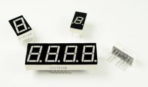 Seven segment displays come in a wide variety of sizes and colors. Red, blue, and green are the easiest colors to find. Sizes range from small 0.56 inch displays up to large 4 inch and even 6.5 inch displays. Some displays have a single digit, and others have two or four.
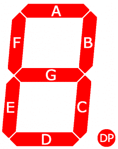
Seven segment displays consist of 7 LEDs, called segments, arranged in the shape of an “8”. Most 7-segment displays actually have 8 segments, with a dot on the right side of the digit that serves as a decimal point.
Each segment is named with a letter A to G, and DP for the decimal point.
Each segment on the display can be controlled individually, just like a regular LED.
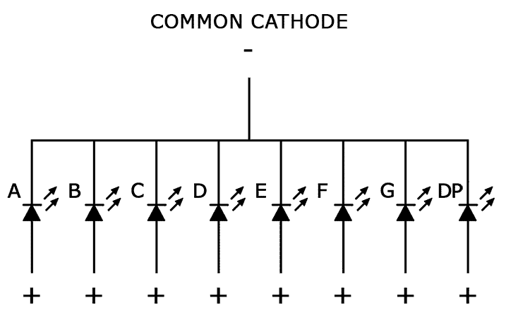
“common cathode display”
In common cathode displays, all of the cathodes are connected to ground and individual segments are turned on and off by switching power to the anodes:
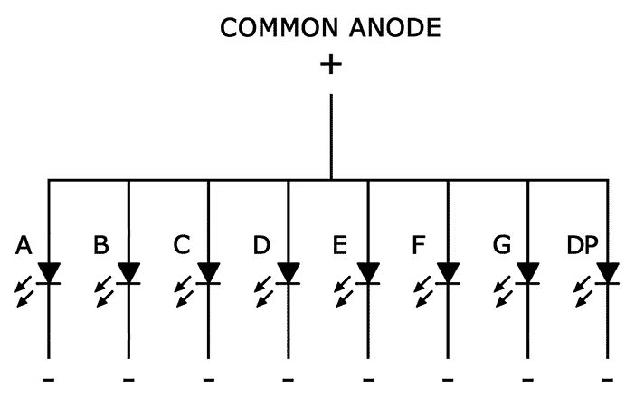
“common anode display”
In common anode displays, all of the anodes are connected to Vcc, and individual segments are turned on and off by switching power to the cathodes:
“how to tell if you have either a common cathode or common anode”
To determine if a display is common anode or common cathode, you can probe the pins with a test circuit constructed like this:
Connect the ground (black) wire to any pin of the display. Then insert the positive (red) wire into each one of the other pins. If no segments light up, move the ground wire over to another pin and repeat the process. Do this until at least one segment lights up.
When the first segment lights up, leave the ground wire where it is, and connect the positive wire to each one of the other pins again. If a different segment lights up with each different pin, you have a common cathode display. The pin that’s connected to the ground wire is one of the common pins. There should be two of these.
If two different pins light up the same segment, you have a common anode display. The pin that’s connected to the positive wire is one of the common pins. Now if you connect the ground wire to each one of the other pins, you should see that a different segment lights up with each different pin.
“determine the pinout”
Now draw a diagram showing the pins on your display. With the common pin connected to the ground wire (common cathode) or positive wire (common anode), probe each pin with the other wire. When a segment lights up, write down the segment name (A-G, or DP) next to the corresponding pin on your diagram.
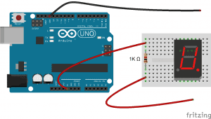
“connecting single digit displays”
Once you have the pin layout figured out, connecting the display to an Arduino is pretty easy. This diagram shows how to connect a single digit 5161AS display (notice the 1K ohm current limiting resistor connected in series with the common pins):
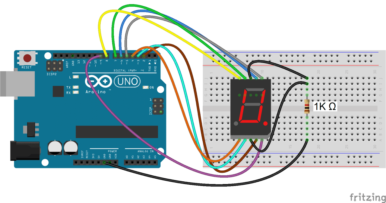
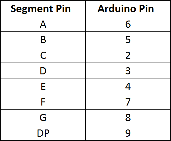
In the example programs below, the segment pins connect to the Arduino according to this table:
“programming single digit displays”
Install the Library
We’ll use a library called SevenSegments to control the display. The SevSeg library works with single digit and multi-digit seven segment displays. You can download the library’s ZIP file from GitHub.
To install it, open the Arduino IDE, go to Sketch > Include Library > Add .ZIP Library, then select the 7-SegmentsDisplay ZIP file downloaded.
“print numbers to display”
This program will print the number “4” to a single digit 7-segment display:
#include "SevenSegments.h" SevenSegments sevseg; void setup() { byte numDigits = 1; byte digitPins[] = {}; byte sevenSegmentPins[] = {6, 5, 2, 3, 4, 7, 8, 9}; bool resistorsOnSevenSegments = true; byte hardwareConfig = COMMON_CATHODE; sevseg.sevenSegmentsBegin(hardwareConfig, numDigits, digitPins, sevenSegmentsPins, resistorsOnSevenSegments); sevenSegments.setBrightness(90); } void loop() { for (int i = 0; i < 10; i++) { sevenSegments.setSevenSegmentsNumber(i, i%2); delay(1000); sevseg.refreshSevenSegmentsDisplay(); } }In this program, we create a sevseg object on line 2.
Pls, note.To use additional displays, you can create another object and call the relevant functions for that object.
The display is initialized with the sevseg.sevenSegmentsBegin() function on line 11. The other functions are explained below:
hardwareConfig = COMMON_CATHODE; This sets the type of display. I’m using a common cathode, but if you’re using a common anode then use COMMON_ANODE instead.
byte numDigits = 1; This sets the number of digits on your display. I’m using a single digit display, so I set it to 1. If you’re using a 4 digit display, set this to 4.
byte digitPins[] = {}; Creates an array that defines the ground pins when using a 4 digit or multi-digit display. Leave it empty if you have a single digit display. For example, if you have a 4 digit display and want to use Arduino pins 10, 11, 12, and 13 as the digit ground pins, you would use this: byte digitPins[] = {10, 11, 12, 13};. See the 4 digit display example below for more info.
byte sevenSegmentsPins[] = {6, 5, 2, 3, 4, 7, 8, 9}; This declares an array that defines which Arduino pins are connected to each segment of the display. The order is alphabetical (A, B, C, D, E, F, G, DP where DP is the decimal point). So in this case, Arduino pin 6 connects to segment A, pin 5 connects to segment B, pin 2 connects to segment C, and so on.
resistorsOnSevenSegments = true; This needs to be set to true if your current limiting resistors are in series with the segment pins. If the resistors are in series with the digit pins, set this to false. Set this to true when using multi-digit displays.
sevenSegments.setBrightness(90); This function sets the brightness of the display. It can be adjusted from 0 to 100.
sevseg.setSevenSegmentsNumber(); This function prints the number to the display. For example, sevseg.setSevenSegmentsNumber(4); will print the number “4” to the display. You can also print numbers with decimal points. For example, to print the number “4.999”, you would use sevseg.setSevenSegmentsNumber(4999, 3);. The second parameter (the 3) defines where the decimal point is located. In this case it’s 3 digits from the right most digit. On a single digit display, setting the second parameter to “0” turns on the decimal point, while setting it to “1” turns it off.
sevseg.refreshSevenSegmentsDisplay(); This function is required at the end of the loop section to continue displaying the number.
Count Up Timer
This simple program will count up from zero to 9 and then loop back to the start:
The code is similar to the previous sketch. The only difference is that we create a count variable “i” in the for statement on line 16 and increment it one number at a time.
The sevenSegments.setSevenSegmentsNumber(i, i%2); function prints the value of i. The i%2 argument divides i by 2 and returns the remainder, which causes the decimal point to turn on every other number.
The count up timer is a nice way to demonstrate the basics of how to program the display, but now let’s try to make something more interesting.
“4-digit 7-segment displays”
So far we have only worked with single digit 7-segment displays. To display information such as the time or temperature, you will want to use a 2 or 4 digit display, or connect multiple single digit displays side by side.
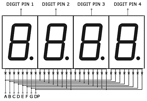
In multi-digit displays, one segment pin (A, B, C, D, E, F, G, and DP) controls the same segment on all of the digits. Multi-digit displays also have separate common pins for each digit. These are the digit pins. You can turn a digit on or off by switching the digit pin.
I’m using a 4 digit 7-segment display with the model number 5641AH, but the wiring diagrams below will also work with the 5461AS.
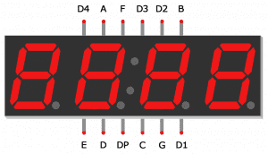
Here is a diagram showing the pinout of these displays:
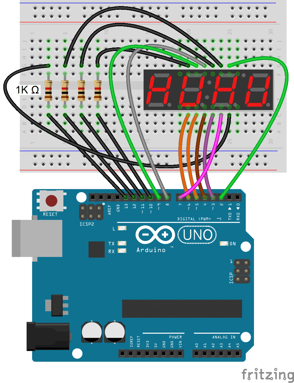
The digit pins D1, D2, D3 and D4 need to be connected to current limiting resistors, since they are the common terminals of the digits. The connections are shown below:
This simple program will print the number “4.999” to the display.
#include "SevSeg.h" SevSeg sevseg; void setup(){ byte numDigits = 4; byte digitPins[] = {10, 11, 12, 13}; byte segmentPins[] = {9, 2, 3, 5, 6, 8, 7, 4}; bool resistorsOnSegments = true; bool updateWithDelaysIn = true; byte hardwareConfig = COMMON_CATHODE; sevseg.begin(hardwareConfig, numDigits, digitPins, segmentPins, resistorsOnSegments); sevseg.setBrightness(90); } void loop(){ sevseg.setNumber(4999, 3); sevseg.refreshDisplay(); }In the code above, we set the number of digits in line 5 byte numDigits = 4;
Since multi-digit displays use digit pins, we also need to define which Arduino pins will connect to the digit pins. Using byte digitPins[] = {10, 11, 12, 13}; on line 6 sets Arduino pin 10 as the first digit pin, Arduino pin 11 to the second digit pin, and so on.
To print numbers with a decimal point, we set the second parameter in sevseg.setNumber(4999, 3); to three, which puts it three decimal places from the right most digit.