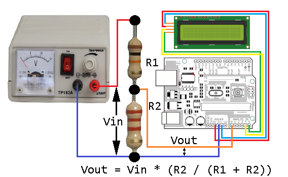
Arduino Uno board contains 6 analog inputs intended for voltage measurement of signals, even if it sholud be more correct to say that the 6 pins of the board can operate in the mode of both discrete pins and analog inputs.
These pins have numbers from 14 to 19. Initially, they are configured as analog inputs, and can be accessed via the names A0-A5. At any time they can be configured to the discrete inputs or outputs.
pinMode (A3, OUTPUT); // Set the discrete output mode for A3
digitalWrite (A3, LOW); // set low state at A3 output
To return to analog input mode:
pinMode (A3, INPUT); // set the analog input mode for A3
“Analog Inputs and pull-up resistors”
Pull-up resistors are connected to the pins of the analog inputs, as well as to the discrete pins. These resistors are turned on by the command:
digitalWrite (A3, HIGH); // switch on the pull-up resistor to the A3 input
The command must be applied to the pin configured in the input mode.
We must remember that the resistor can affect the level of the input analog signal. The current from the 5 V power supply, through a pull-up resistor, will cause a voltage drop across the internal resistance of the signal source. So it is better to turn off the resistor.
Analog-digital converter of Arduino board
The actual measurement of the voltage at the inputs is made by an analog-to-digital converter (ADC) with 6 channels multiplexer. The ADC has a resolution of 10 bits, which corresponds to the code at the output of the converter 0 … 1023. The measurement error is not more than 2 units of the lower digit.
To maintain maximum accuracy (10 bits) it is necessary that the internal resistance of the signal source does not exceed 10 kΩ. This requirement is especially important when using resistor dividers connected to the analog inputs of the board. The resistance of the resistors of the dividers can not be too large.
Functions for working with analog inputs
int analogRead (port)
Reads the voltage value at the specified analog input. The input voltage range from 0 to the level of the reference voltage source (often 5 V) converts to code from 0 to 1023.
With a reference voltage of 5 V, the resolution is 5 V / 1024 = 4.88 mV.
It takes about 100 µs to convert.
int inputCod; // input voltage code
float inputVoltage; // input voltage, V
inputCod = analogRead (A3); // read the voltage at the A3 input
inputVoltage = ((float) inputCod * 5. / 1024.); // recalculate code to voltage (V)
void analogReference (type)
Sets the reference voltage for the ADC. It determines the maximum value of the voltage on the analog input that the ADC can correctly convert. The magnitude of the reference voltage also determines the code to voltage conversion factor:
Input voltage = ADC code * reference voltage / 1024.
Type can have the following values:
- DEFAULT – the reference voltage is equal to the controller supply voltage (5 V or 3.3 V). For Arduino UNO R3 – 5 V.
- INTERNAL – internal reference voltage of 1.1 V for boards with ATmega168 and ATmega328 controllers, for ATmega8 – 2.56 V.
- INTERNAL1V1 – internal reference voltage of 1.1 V for Arduino Mega controllers.
- INTERNAL2V56 – internal reference voltage of 2.56 V for Arduino Mega controllers.
- EXTERNAL – external reference voltage source, is connected to the AREF input.
analogReference (INTERNAL); // reference voltage is 1.1 V
It is recommended that an external reference voltage source be connected through a current-limiting resistor of 5 kΩ.


