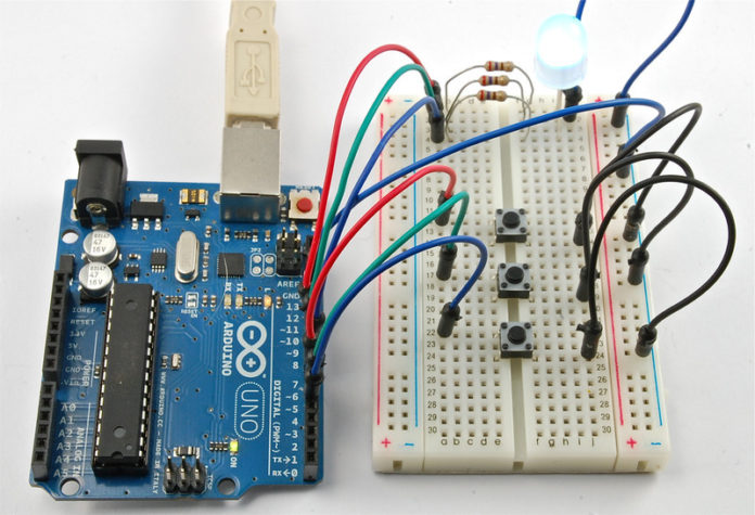
There are actually two types of RGB Led’s; the common cathode one and the common anode one. In the common cathode RGB Led, the cathode of all the Led’s is common and we give PWM signals to the anode of Led’s while in the common anode RGB Led, the anode of all the Led’s is common and we give PWM signals to the cathode of Led’s.

The one that we are going to use is the common cathode RGB Led. So, we will connect the common pin to the GND of Arduino and the other three leads of the Led’s to the PWM pins of Arduino.
Again, we have three output pins to control the LED. These are PWM pins so that we can control how much power goes to each color of the LED.
There are three other pins needed, one for each of the buttons and these are configured in ‘setup’ to be inputs that are pulled up to HIGH, unless the button is pressed, which will cause them to become LOW.
After the pin definition, there is another little group of variables called ‘red’, ‘green’ and ‘blue’.
int red = 0;
int blue = 0;
int green = 0;
These variables are used to hold the current values for the intensity of each of the LED channels. So, if ‘red’ is 0 then the red part of the LED will be off. However, if it is 255 then it will be at maximum brightness.
The ‘loop’ function is in two parts. The first part checks the buttons and makes any necessary changes to ‘red’, ‘green’ or ‘blue’ depending on the button. Each button works in the same way, just for a different color. The section for checking the red button is like this:
if (digitalRead(redSwitchPin) == LOW)  {
    red ++;
    if (red > 255)
        red = 0;
}
If, when we carry out a ‘digitalRead’ on the red switch pin, we find it is LOW, then that means the button is pressed, so we add 1 to ‘red’. The command ++ adds one to a variable.
However, we need to be careful here, because the maximum value that you can use for PWM is 255. So on the next line, we check to see if we have gone over the limit, and if we have then red is set back to 0, so we start over.
The second part of the ‘loop’ function carries out the ‘analogWrite’s to each of the LED colors.
analogWrite(redLEDPin, red);
analogWrite(greenLEDPin, green);
analogWrite(blueLEDPin, blue);
Finally there is a short delay at the end of the loop, that slows down the color changing to a manageable speed.
Other Things to Do
Try removing the delay at the end of ‘loop’. You can do this by ‘commenting out’ the delay line by putting // at the start of the line like this:
analogWrite(blueLEDPin, blue); // delay(10);}
This is a useful technique, because when you find out that you need to put the line back in again, you can do so, just by taking the // away again.
Without the delay, you will find that basically, whenever you release the button, you will be left with a random level of brightness for that color. What is happening is that the it is cycling through the brightness levels so fast, that you have no chance of actually controlling it.
Another experiment you could make would be to change the function of the three buttons so that they control the LED as if it was a traffic signal.
Try to make it so that the top button turns the LED fully green, the middle button Orange and the bottom button red.
End of Post


