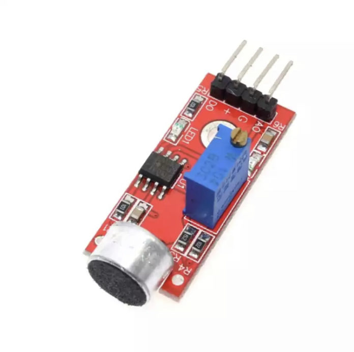
The microphone sound sensor, as the name says, detects sound. It gives a measurement of how loud a sound is.

It has four pins that needs to be connected to your Arduino. The top one(if you look at the image above), is AO. This should be connected to the analog input 0 on the Arduino(A0). The one beside that is GND, which is connected to ground, the VCC is connected to +5V, and the last one is DO – which is the digital output of the module, and should be connected to digital pin 2 on the Arduino.
Here is the connection described with a table:

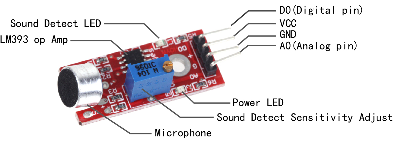
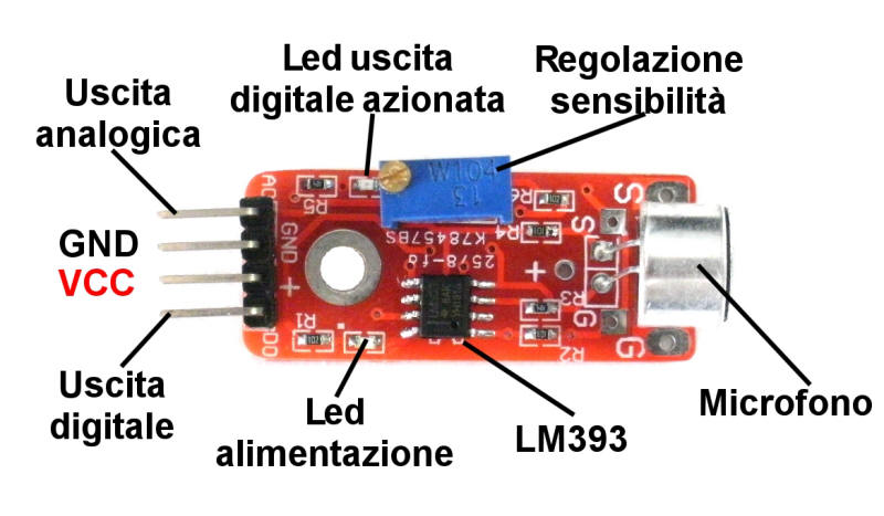
On the top of the sound sensor is a little flathead screw you can turn to adjust the sensitivity and analog output of the sound sensor. To calibrate the sound sensor you can run some music the background and keep turning it until you start seeing the sensor-LED on the module starts blinking with the rhythm.
How Electret Microphones work?
nside the microphone is the thin diaphragm, which is actually one plate of a capacitor. The second plate is the backplate, which is close to and parallel to the diaphragm.
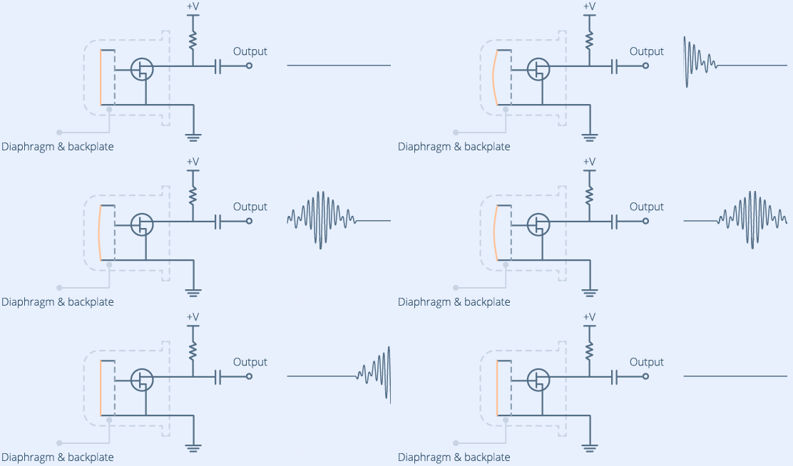
When you speak into the microphone, sound waves created by your voice strike the diaphragm, causing it to vibrate.
When the diaphragm vibrates in response to sound, the capacitance changes as the plates get closer together or farther apart.
As the capacitance changes, the voltage across the plates changes, which by measuring we can determine the amplitude of the sound.
The sound sensor is a small board that combines a microphone (50Hz-10kHz) and some processing circuitry to convert sound waves into electrical signals.
WIRING

Wiring LEDs
Now if you are only going to use one LED, connect your resistor from ground to the shorter side of the LED, and the long side of the LED to digital pin 3 on the Arduino.
So basically Arduino Digital Pin(3-9) –> Positive Side of LED –> Negative Side of LED –> 333 ohm resistor –> Arduino Ground Pin(GND)
Adjusting pot
The following sketch has ‘Serial’ commented out, for instance “Serial.begin(9600)” and “Serial.print(“Analog: “);”
Pls, note that:
If you have even more LEDs, keep doing the same but connect the next one to digital pin 4, the next one to digital pin 5 etc. I’ve written code to support 7 LED lights, which means you use digital pin 3 all the way to 9 for your LEDs.
The reason I just didn’t connect the LEDs in parallel and then to only one digital pin, is because on for instance the Uno’s digital pins doesn’t have enough juice to fully power all those power hungry LEDs. You could use a transistor or a 7HC595N, but I just wanted to do a simple sound sensor tutorial so I didn’t include any of that in this post.
Now remove the all the comment-slashes which has ‘Serial’ commented out, for instance “Serial.begin(9600)” and “Serial.print(“Analog: “);”.
When you did that upload the code to your Arduino: this will enable serial output which you can view by using the Serial Monitor from the Arduino software.
Pls, open the Serial Monitor by going to Tools->Serial Monitor or pressing the magnifying glass-button in the Arduino software window. What prints out is the analog and digital values of from the sound sensor module. The analog value should spike up when a noise occurs and stabilize when it gets quiet again. Now in the code there is an “int threshold = 532;” line that needs to be changed to something very close but higher than the value you get from the Serial Monitor when it is quiet around you.
As an example, if you see an analog value of 253, then threshold should be changed to perhaps 255 or 257. When a sound occurs, the analog value will rise and go above the threshold value. When that happens your LEDs will turn on. When it gets quiet again the analog value will go back to 253 and the LEDs go dark again. When you think the calibration is finished, recomment the Serial-commands and reupload the code to your Arduino. Commenting out any Serial-commands is important due to the Serial commands take very much processing power from the Arduinos, and will affect the performance of the sound sensor and blinking.
LEDS BAR
These 10-segment bar graph LEDs have many uses. With a compact footprint, simple hookup, they are easy for prototype or finished products. Essentially, they are 10 individual blue LEDs housed together, each with an individual anode and cathode connection.
They are also available in yellow, red, and green colors.
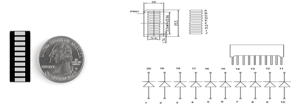
Pls, note − The pin out on these bar graphs may vary from what is listed on the datasheet. Rotating the device 180 degrees will correct the change, making pin 11 the first pin in line.

Open Arduino IDE, click File -> Sketchbook -> sound_sensor example. Hereinafter the sketch:
GROOVE BAR
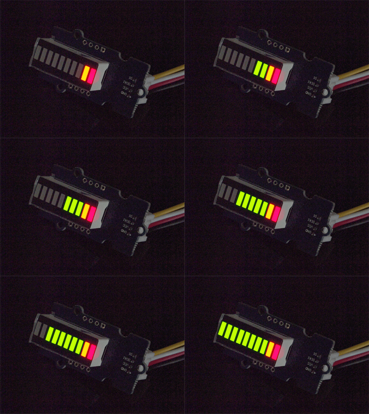
THE SKETCH
Load “Level” example via the path: File → Examples → Grove LED Bar → Level
LEVEL METER
/*
 * Noise Monitor
 * Sketch for an Arduino gadget that detects the audio level.
 */

#define SENSOR_PIN A0 // select the input pin for the input device

#define NUMBER_OF_LEDS 10
including the following code:
Clapper,
Clap Sensitive Light Control
“Clapper” that turns on AC powered devices with the clap of your hands.

First you need to supply power to the sensor and the relay module. Connect their VCC pins to the 5V pin on the Arduino and GND to ground.
Next connect the output pin (OUT) on the sound sensor to the digital pin #7 on your Arduino, and control pin (IN) on the relay module to the digital pin #8.
You’ll also need to place the relay module in line with the AC powered device you’re attempting to control. You’ll have to cut your live AC line and connect one end of the cut wire (coming from the wall) to COM and the other to NO.

const int buttonPin = 2;
const int ledPin = 0;

int buttonstate;
int ledstate;

void setup() {
    pinMode(ledPin, OUTPUT);
    pinMode(buttonPin, INPUT);
}

void loop() {

    buttonstate = digitalRead(buttonPin);
    ledstate = digitalRead(ledPin);

    if (ledstate == HIGH && buttonstate == LOW) {
        delay(250);
        digitalWrite(ledPin, LOW);
    }
    if (ledstate == LOW && buttonstate == LOW) {
        delay(250);
        digitalWrite(ledPin, HIGH);
    }
}
The sketch begins with the declaration of the Arduino pin to which the sensor’s OUT pin is connected.
#define sensorPin 7
Next, we define a variable called lastEvent that stores the time since the clap detected. It will help us eliminate spurious sounds.
unsigned long lastEvent = 0;
In the Setup section, we declare the signal pin of the sensor as input. We also setup the serial monitor.
pinMode(sensorPin, INPUT);
Serial.begin(9600);
In the loop section, we first read the digital output from the sensor.
int sensorData = digitalRead(sensorPin);
When the sensor detects any sound loud enough to cross the threshold value, the output goes LOW. But we have to make sure that the sound is due to clapping and not due to the spurious background noise. So, we wait for 25 milliseconds. If output remains LOW for more than 25 milliseconds, we declare that the clap is detected.
Control Devices with a Clap
Explaining the sketch
If you compare this sketch with our previous one you’ll notice many similarities, except few things.
At the start we declare the Arduino pin to which the relay’s control pin (IN) is connected. We have also defined a new variable relayState to store the state of relay.
#define relayPin 7

boolean relayState = false;
In the Setup, we define the relayPin as being output.
pinMode(relayPin, OUTPUT);
Now when we detect the sound of the clap, instead of printing the message on the serial monitor, we just toggle the state of the relay.
relayState = !relayState;
digitalWrite(relayPin, relayState ? HIGH : LOW);
Troubleshooting
If the Sound Sensor is misbehaving, try the following steps.
- Double check that the power supply is clean. Because the sound sensor is an analog circuit, it’s more sensitive to noise on the power supply.
- The electret microphone on the sound sensor is also sensitive to mechanical vibration and wind noise. Mounting it with a resilient material can help absorb vibration.
- The sensing range of this sound sensor is very small, probably 10 inches, so you have to make a noise much closer to get a good response.
Control a RGB LED
End of Post


