


A Microcontroller uses many different protocols to communicate with various sensors and peripherals. There are many protocols for wireless and wired communication. Most of the things that we use now can be automated: to design automated devices first we need to know about the sensors, these are the modules/devices which are helpful in making things done without human intervention. Even the mobiles or smartphones which we daily use will have some sensors like hall sensor, proximity sensor, accelerometer, touch screen, microphone etc. These sensor acts as eyes, ears, nose of any electrical equipment which senses the parameters in outside world and give readings to devices or Microcontroller.
What is a sensor?
The sensor can be defined as a device which can be used to sense/detect the physical quantity like force, pressure, strain, light etc and then convert it into desired output like the electrical signal to measure the applied physical quantity. In few cases, a sensor alone may not be sufficient to analyze the obtained signal. In those cases, a signal conditioning unit is used in order to maintain sensor’s output voltage levels in the desired range with respect to the end device that we use.
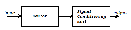
In signal conditioning unit, the output of the sensor may be amplified, filtered or modified to the desired output voltage. For example, if we consider a microphone it detects the audio signal and converts to the output voltage (is in terms of millivolts) which becomes hard to drive an output circuit. So, a signal conditioning unit (an amplifier) is used to increase the signal strength. But the signal conditioning may not be necessary for all the sensors like photodiode, LDR etc.
Most of the sensors can’t work independently. So, sufficient input voltage should be applied to it. Various sensors have different operating ranges which should be considered while working with it else the sensor may get damaged permanently.
Types of Sensors:
Let us see the various types of sensors that are available in the market and discuss their functionality, working, applications etc. We will discuss various sensors like:
- Light Sensor
- IR Sensor (IR Transmitter / IR LED)
- Photodiode (IR Receiver)
- Light Dependent Resistor
- Temperature Sensor
- Thermistor
- Thermocouple
- Pressure/Force/Weight Sensor
- Strain Gauge (Pressure Sensor)
- Load Cells (Weight Sensor)
- Position Sensor
- Potentiometer
- Encoder
- Hall Sensor (Detect Magnetic Field)
- Flex Sensor
- Sound Sensor
- Microphone
- Ultrasonic Sensor
- Touch Sensor
- PIR Sensor
- Tilt Sensor
- Accelerometer
- Gas Sensor
We need to select the desired sensor based on our project or application. As said earlier in order to make them work proper voltage should be applied based on their specifications.
SPI, A Serial Communication PROTOCOL
The most commonly used communication technique is Serial Communication, that’s the process of sending data one bit at a time, sequentially, over a communication channel or bus.
There are many types of serial communication like UART, CAN, USB, I2C and SPI communication: here we learn about SPI protocol and how to use it in Arduino.
SPI (Serial Peripheral Interface) is a serial communication protocol. SPI interface was found by Motorola in 1970. SPI has a full duplex connection, which means that the data is sent and received simultaneously. That is a master can send data to slave and a slave can send data to master simultaneously. SPI is synchronous serial communication means the clock is required for communication purpose.
A SPI has a master/Slave communication by using four lines. A SPI can have only one master and can have multiple slaves. A master is usually a microcontroller and the slaves can be a microcontroller, sensors, ADC, DAC, LCD etc.
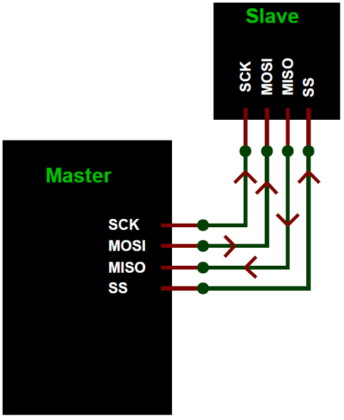
SPI has following four lines MISO, MOSI, SS, and CLK
- MISO (Master in Slave Out) – The Slave line for sending data to the master.
- MOSI (Master Out Slave In) – The Master line for sending data to the peripherals.
- SCK (Serial Clock) – The clock pulses which synchronize data transmission generated by the master.
- SS (Slave Select) –Master can use this pin to enable and disable specific devices.
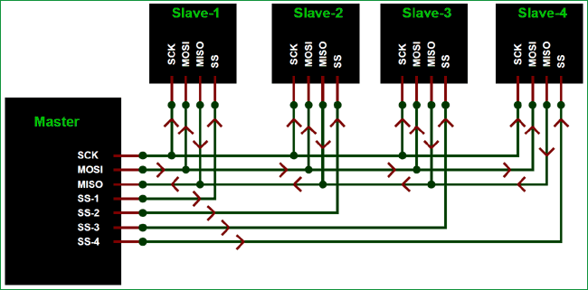
To start communication between master and slave we need to set the required device’s Slave Select (SS) pin to LOW, so that it can communicate with the master. When it’s high, it ignores the master. This allows you to have multiple SPI devices sharing the same MISO, MOSI, and CLK lines of master. As you can see in the above image there are four slaves in which the SCLK, MISO, MOSI are common connected to master and the SS of each slave is connected separately to individual SS pins (SS1, SS2, SS3) of master. By setting the required SS pin LOW a master can communicate with that slave.
SPI Pins in Arduino UNO
End Of Post