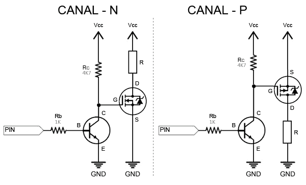
The interfacing of power devices like BJTs, and MOSFETs with Arduino output is a crucial configuration which allows switching high power loads through low power outputs of an Arduino.
In this article we elaborately discuss the correct methods of using or connecting transistors like BJTs and mosfets with any microcontroller or an Arduino.
Such stages are also referred to as “Level Shifter” because this stage changes the voltage level from a lower point to a higher point for the relevant output parameter. For example here the level shift is being implemented from Arduino 5V output to MOSFET 12V output for the selected 12V load.
No matter how well programmed or coded your Arduino may be, if it’s not correctly integrated with a transistor or an external hardware, could result in inefficient operation of the system or even damage to the components involved in the system.
Therefore, it becomes extremely important to understand and learn the right methods of using external active components like mosfets and BJTs with a microcontroller, so that the final outcome is effective, smooth and efficient.
Before we discuss the interfacing methods of transistors with Arduino, it would be useful to learn the basic characteristics and working of BJTs and mosfets.
Electrical Characteristics of Transistors (Bipolar)
BJT stands for bipolar junction transistor.
The basic function of a BJT is to switch ON an attached load in response to an external voltage trigger. The load is supposed to be mostly heavier in current compared to the input trigger.
Thus, the basic function of a BJT is to switch ON a higher current load in response to a lower current input trigger.
Technically, this is also called biasing of the transistor, which means using current and voltage to operate a transistor for an intended function, and this biasing has to be done in the most optimal way.
BJTs have 3 leads or 3 pins, namely base, emitter, collector.
The base pin is used for feeding the external input trigger, in the form of small voltage and current.
The emitter pin is always connected to the ground or the negative supply line.
The collector pin is connected to the load via the positive supply.
BJTs can be found with two types of polarities, NPN and PNP. The basic pin configuration is the same for both NPN and PNP as explained above, except the DC supply polarity which becomes just the opposite.
Final Thoughts
By now you should have comprehensively understood the correct method of connecting BJTs and mosfets with a microcontroller or an Arduino.
You might have noticed that we have mostly used NPN BJTs and N-channel mosfets for the integrations, and have avoided using the PNP and P-channel devices. This is because NPN versions work ideally like a switch and is easy to comprehend while configuring.
It’s like driving a car normally in the forward direction, rather than looking behind and driving it in the reverse gear. In both ways the car would operate and move, but driving in the reverse gear is much inefficient and doesn’t make sense. The same analogy applies here, and using NPN or N-channel devices become a better preference compared to PNP or P-channel mosfets.
End Of Post


