


Fun with 8×8 LED Matrix
To summarise the guide:
- A shift register allows you to have 8 outputs while only using 3 pins on the Arduino
- You send a byte to the shift register which has 8 bits (e.g. 10010000)
- You can combine shift registers so instead of having only 8 outputs you can have 16 when using 2, 24 when using 3, and so on
- When combining shift registers, instead of sending out the 8 bits to the first register and 8 to the second register it’s actually reversed, so the first 8 bits you send are actually for the second register and the next 8 bits go to the first register
It seems like the Arduino ShiftOut code examples code was different almost in each example so which way is the easiest to doing this? I found the example that used bitWrite to be the easiest to use as below.
byte bitsToSend = 0;
digitalWrite(latchPin, LOW);
bitWrite(bitsToSend, 0, HIGH);
bitWrite(bitsToSend, 3, HIGH);
shiftOut(dataPin, clockPin, MSBFIRST, bitsToSend);
digitalWrite(latchPin, HIGH);
This is an example to use with only 1 shift register. Firstly you assign the variable bitsToSend as a byte which is 8 bits (e.g. 00000000), then you put the latchPin to low to tell the shift register that you will be sending the new state of the outputs. Now is where the bitWrite function comes in, bitWrite modifies the bitsToSend variable and turns on the bit number we specify as 1. So in our example, the 3rd line in our program would now change bitsToSend from 00000000 to 10000000.
The next line would change it from 10000000 to 10010000, so you see it has the number 3 in our bitWrite which basically says count to 4 (because we start at 0) and assign a 1 to the number you reach.
Now that we have our byte to send, we use the shiftOut function to send the byte to the shift register (which sends each bit one by one) and then we turn latchPin back on to say we are done and that the shift register can now enable the outputs we’ve specified which are outputs 0 and 3, so the LEDs assigned to those outputs would light up as per the layout below (it’s been simplified so it’s easier to understand)
So by now you should have an understanding of how shift registers are used, we’ll jump into using them to controller a LED Matrix of 64 LEDs (8×8).
Parts used
- 2 x 74HC595 Serial Shift Register
- 1 x ULN2803A Darlington Array (of Transistors)
- 8 x 220 Ohm 1/4W Resistor
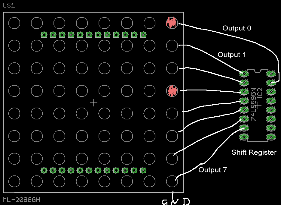
Schematic
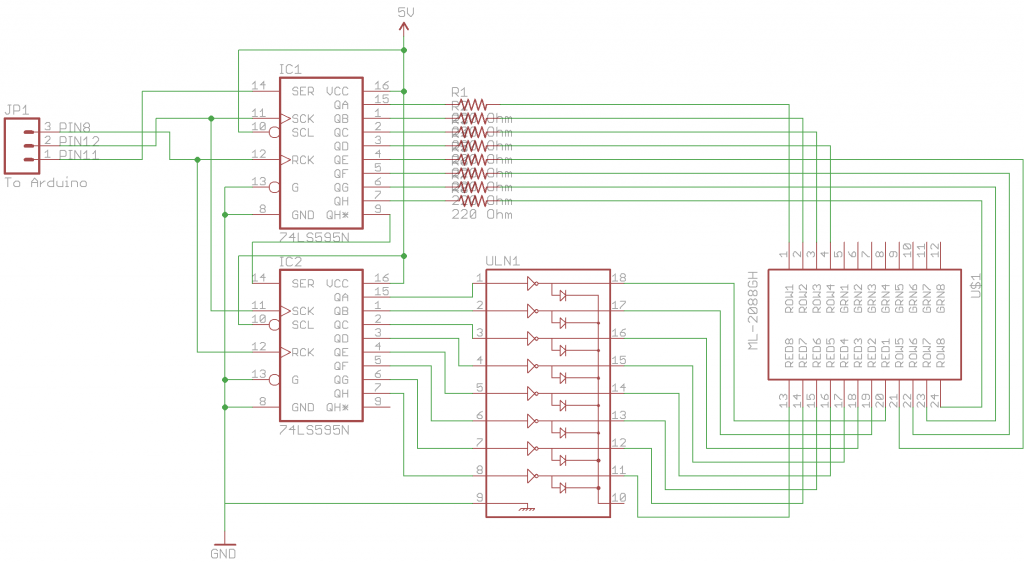
So lets read our schematic, with our LED Matrix we have 8 rows (ROW1, etc) and 8 columns (RED1, etc), row 0 and column 0 for us will start at the top left. The first shift register controls the rows and the second shift register controls the darlington array which in turn controls the columns. We know how the rows work with the single shift register, so how does the darlington array work with the shift register?
We know how transistors work from our previous posts, the darlington array has Inputs, Outputs and the ground. All we need to do is connect the outputs from the shift register to the darlington array, connect the columns to the darlington array outputs, then the ground and you’re done. Simple hey?
How it works
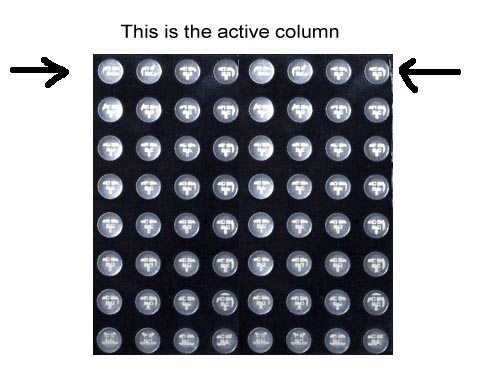
We tell the Arduino to send out 2 bytes (10000000 00010000) to the first shift register. The first byte is passed on to the second shift register (10000000) which controls the columns, this byte gets processed as turn on output 0. Output 0 is enabled which switches on the first transistor in the ULN chip, this then allows the column 0 of the LED matrix to be activated and allow current to flow into it.
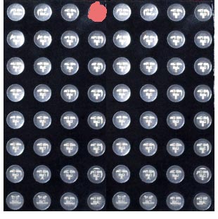
Now we go back to our first shift register and that has received the second byte (00010000) which controls the rows and says turn on output 3 which turns on the LED as below.
And that’s it! Now you might be wondering how can we turn on say the led on row 3, column 0 and then row 6, column 1? It can be achieved by turning on each column really fast; by fast I mean every 2 milliseconds (ms). So each 2ms, we turn on the next column and the row outputs associated with it.