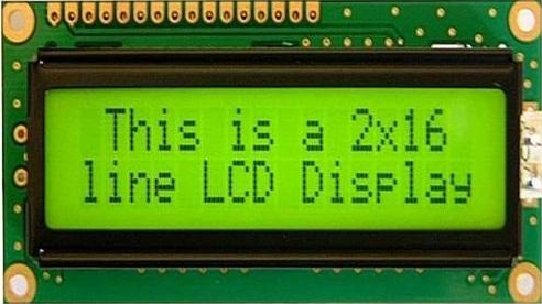
The LCD displays might be the perfect fit to display status messages or sensor read.
Looking closely, you can actually see the little rectangles for each character on the display and the pixels that make up a character. Each of these rectangles is a grid of 5×8 pixels.
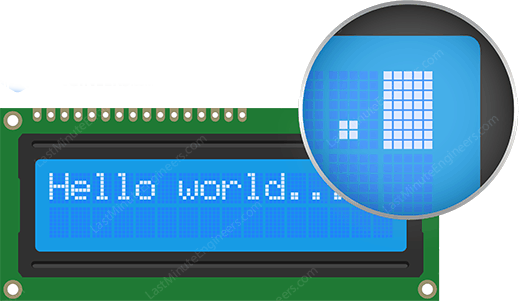
Although they display only text, they do come in many sizes and colors: for example, 16×1, 16×4, 20×4, with white text on blue background, with black text on green and many more.
16×2 Character LCD Pinout
The good news is that all of these displays are ‘swappable’ – if you build your project with one you can just unplug it and use another size/color LCD of your choice. Your code may have to adjust to the larger size but at least the wiring is the same!
That’s all!

Explain the sketch
The sketch starts by including LiquidCrystal library. As mentioned earlier in this tutorial, the Arduino community has a library called LiquidCrystal that makes programming the LCD module less difficult.
// include the library
#include <LiquidCrystal.h>
Next we have to create an LiquidCrystal object. This object uses 6 parameters and specifies which Arduino pins are connected to the LCD’s RS pin, Enable pin, and data pins: d4, d5, d6, and d7.
// Creates an LCD object. Parameters: (rs, enable, d4, d5, d6, d7)
LiquidCrystal lcd(12, 11, 5, 4, 3, 2);
Now that you have declared a LiquidCrystal object, you can access special methods (aka functions) that are specific to the LCD.
In the ‘setup’ function: we will use two functions: The first function is begin() . This is used to specify the dimensions of the display i.e. how many columns and rows the display has. If you are using 16×2 character LCD, pass the parameters 16 & 2; If you are using 20×4 LCD, pass the parameters 20 & 4.
The second function is clear() .This clears the LCD screen and moves the cursor to the upper left corner.
lcd.begin(16, 2);
lcd.clear();
In the ‘loop’ function: we will use the print() function which displays the message that we see on the first line of the screen.
// Print a message to the LCD.
lcd.print(" Hello world!");
Following that we will set the cursor position to second row, by calling function setCursor() The cursor position specifies the location where you need the new text to be displayed on the LCD. The upper left corner is considered col=0, row=0.
lcd.setCursor(0, 1);
lcd.print(" LCD Tutorial");
Other useful functions in LiquidCrystal Library
There are a few useful functions you can use with LiquidCrystal object. Few of them are listed below:
- If you just want to position the cursor in the upper-left of the LCD without clearing the display, use
home() - There are many applications like turbo C++ compiler or notepad++, in which pressing ‘insert’ key on the keyboard changes cursor. Just like that you can change the cursor on the LCD using
blink()orlcd.cursor(). blink()function displays the blinking block of 5×8 pixels, whilelcd.cursor()displays an underscore (line) at the position to which the next character will be written.- You can use the
noBlink()function to turns off the blinking LCD cursor andlcd.noCursor()to hide the LCD cursor. - You can scroll the contents of the display one space to the right using
lcd.scrollDisplayRight()or one space left usinglcd.scrollDisplayLeft(). If you want to scroll the text continuously, you need to use these functions inside a ‘for loop’.
Using a Keypad Shield
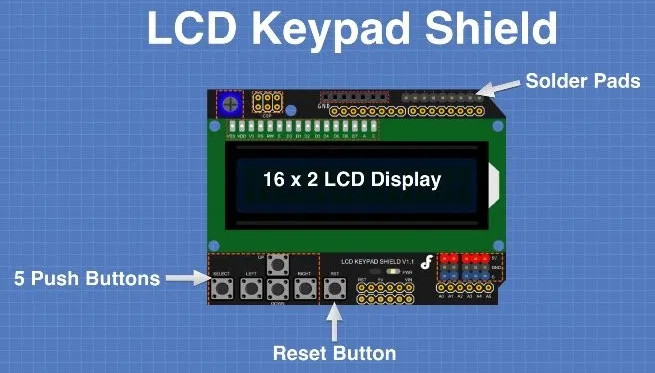
The LCD Keypad Shield is available from several different manufacturers. The device fits onto an Arduino Uno or an Arduino Mega and simplifies adding an LCD display to your project.
LCD Keypad Shield Push Button Operation
The LCD Keypad Shield has 6 push buttons, labeled as follows:
- Right
- Left
- Up
- Down
- Select
- Reset
The Reset button is simply connected to the Arduino Reset pin and works just like the Reset button on the Arduino itself. This is common on many shields as the shields physically cover the Reset button.
The other five push buttons can really be used for anything you’d like to use them for. And the way they are hooked up is very interesting, at least it is to me!
At first glance you might expect that the push buttons simply connect to some of the Arduino digital I/O pins. But that’s not how they work.
Instead the buttons are connected to a resistor array that acts as a voltage divider. The entire array is connected to the Arduino’s analog A0 pin. One pin for five push buttons.
Here is the button arrangement:
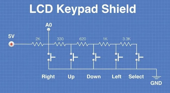
Pressing each button will send a voltage to the analog A0 pin. Because of the arrangement of the resistors each button will send a different voltage to the analog pin. By measuring the voltage level you can determine which button was pressed.
Simple yet ingenious!
Using the Arduino analogRead function on pin A0 the following readings are obtained for each push button:
- Right – 0
- Up – 144
- Down – 329
- Left – 504
- Right – 741
We can use these values to determine which button has been pressed. We will do that in our demo sketch in a moment.
LCD Keypad Shield Connections
Internally the LCD Keypad has the following connections:
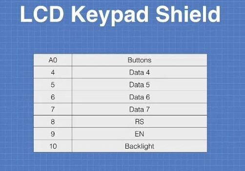
Note that the LCD is being used in 4-wire mode. The LCD itself is the same one used on the LCD1602 module, so all of the code for that module will work with the LCD Keypad Shield as well.
Now that you know how the LCD Keypad module works and which Arduino pins it uses all that remains is to install it onto your Arduino and load the demo sketch.
One thing – once the shield is installed on the Arduino you won’t have easy access to the unused I/O pins to connect any sensors or output devices you may want to use (although the demo sketch doesn’t need anything else connected). There are a couple of ways to get around this:
- Solder some pins to the solder pads on the LCD Keypad display, this is exactly what they are for.
- Use a shield that exposes the pins for prototyping before you install the LCD Keypad shield. In the video associated with this article I use a “Screw Shield” that brings all of the Arduino I/O pins out to a series of screw connectors. There are other similar shields. Using one of these shields is the easiest way to work with the LCD Keypad shield, as well as other Arduino shields.
End Of Post


