


Here you will learn how to use the Light Dependent Resistor Module.
Light Dependent Resistor Module is very common in our daily life. It ismainly used in intelligent switch so as to bring convenience to our life. At the same time, in our daily life, we also use it in electronic design. So in order to use it in a better, we provide
the corresponding modules to help us to use it moreconveniently andefficiently.
An LDR or “Light Dependent Resistor” is a resistor where the resistance decreases with the strength of the light.
Light Dependent Resistors (LDR) are also called photoresistors. They are made of high resistance semiconductor material. When light hits the device, the photons give electrons energy; this makes them jump into the conductive band and thereby conduct electricity.
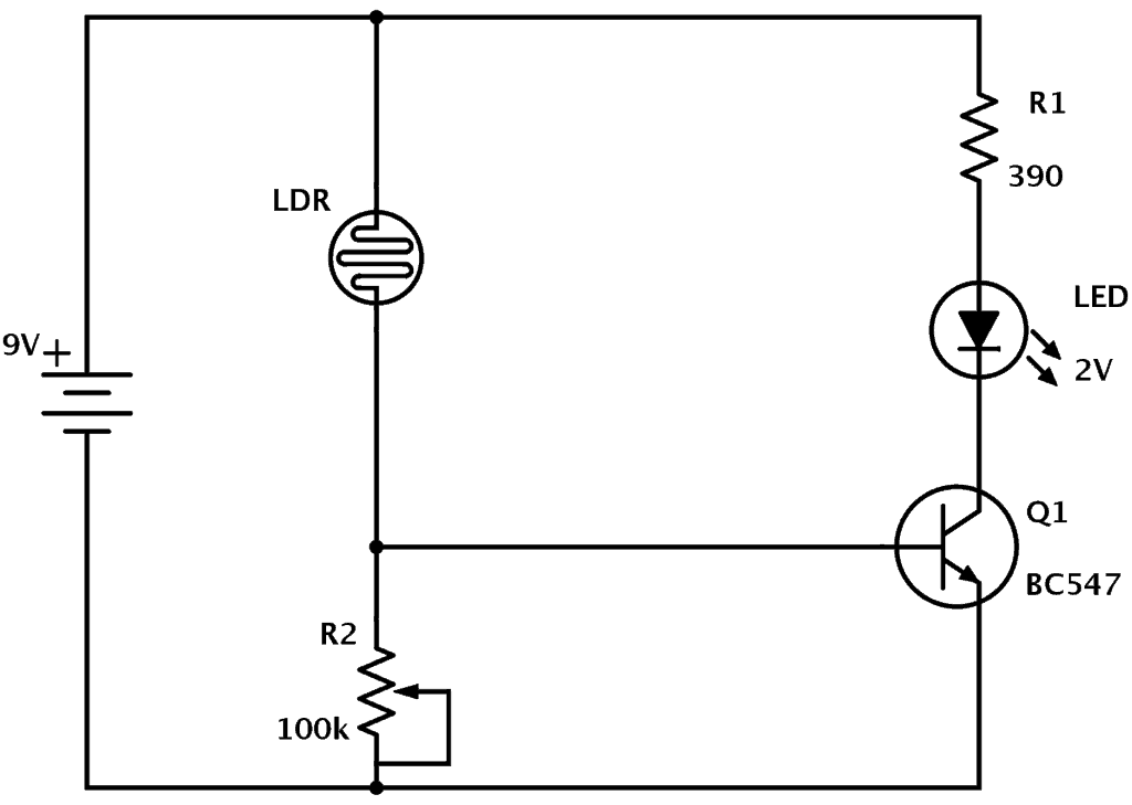
When it’s light, the LDR has low resistance. This makes the voltage at the base of the transistor higher. High enough to turn the transistor ON. Because the transistor is turned on, current flows through the transistor. It flows from the positive battery terminal, through R1, the LED, and the transistor down to the negative battery terminal. This makes the LED light up.
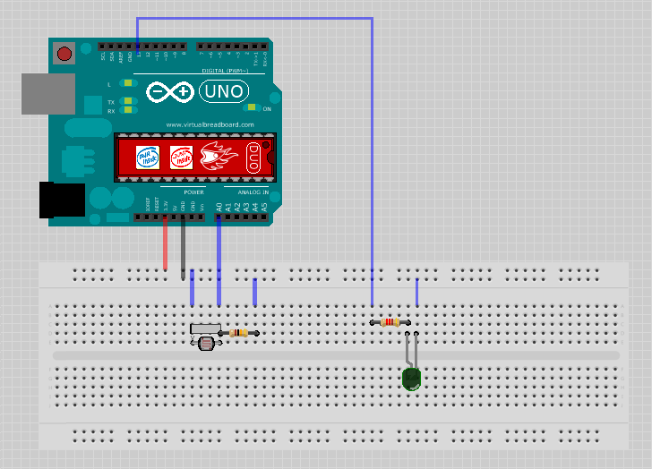
Wiring
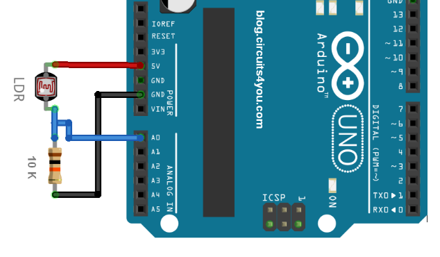
- Connect the 3.3v output of the Arduino to the positive rail of the breadboard
- Connect the ground to the negative rail of the breadboard
- Place the LDR on the breadboard
- Attach the 10K resistor to one of the legs of the LDR
- Connect the A0 pin of the Arduino to the same column where the LDR and resistor is connected [Since the LDR gives out an analog voltage, it is connected to the analog input pin on the Arduino. The Arduino, with its built-in ADC (Analog to Digital Converter), then converts the analog voltage from 0-5V into a digital value in the range of 0-1023].
- Now connect the other end of the 10K resistor to the negative rail
- And the the second (free) leg of the LDR to the positive rail
Now, as we want our circuit to do something in the real world other than just displaying the values on the computer screen we will be attaching a LED to the circuit. The LED will turn on when its dark and will go off when its bright. To achieve this we will:
- Place the LED on the breadboard
- Connect the 220ohm resistor to the long leg (+ve) of the LED
- Then we will connect the other leg of the resistor to pin number 13 (digital pin) of the Arduino
- and the shorter leg of the LED to the negative rail of the breadboard
The Sketch
const int ledPin = 13;

const int ldrPin = A0;

void setup() {

   Serial.begin(9600);

   pinMode(ledPin, OUTPUT);

   pinMode(ldrPin, INPUT);

}

void loop() {

   int ldrStatus = analogRead(ldrPin);

   if (ldrStatus <= 200) {

      digitalWrite(ledPin, HIGH);

      Serial.print("Its DARK, Turn on the LED : ");

      Serial.println(ldrStatus);

   } else {

      digitalWrite(ledPin, LOW);

      Serial.print("Its BRIGHT, Turn off the LED : ");

      Serial.println(ldrStatus);

   }

}
A Luxmeter
Build a working circuit and program an LDR light sensor to be able to read sunlight and print it on your computer screen.
A luxmeter is a device that measures illuminance and luminous emittance using the SI unit of lux.
It effectively measures the amount of power from the light falling on a given unit of area, except that the power measurement is weighted to reflect the sensitivity of the human eye to varying wavelengths of light.
A simpler way to describe a lux meter is to say that it measures how bright the light falling on the sensor is.

The following block diagram shows the steps on how the LDR reads the lux and to help make the arduino read the values read from the LDR then print the lux on your screen.

How to characterize an LDR
Characterizing the LDR
- Plug the LDR into your breadboard and ensure that the flat part of the sensor is parallel with the ground.
- Connect the DMM to the LDR’s leads and set it to the DMM to measure resistance.
- Place your commercial LDR’s sensor beside the LDR.
- Ensure that the same levels of light fall on the two sensors, then record a reading of the light meter lux and the LDR resistance.
- Repeat this process for several different lighting levels from very dark (close to 0 lux) to very bright (thousands of lux). [Pls, note. It’s important that you do your best to ensure that both sensors get the same amount of light at all of these different light levels.]
- Transfer your readings to a spreadsheet (or you can just enter them directly while you are making measurements)
- Make a plot of the illuminance (lux) as a function of resistance.
- Download the spreadsheet which will create the plot.
- Perform all of the necessary analysis from your entries.
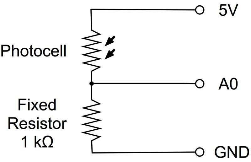
A simple voltage divider circuit
The voltage divider circuit is the crux of our sensor circuit. The 5 volt supply is split between the LDR and the 5 kohm resistor. As the LDR’s resistance changes, the fraction of the voltage across the two resistors changes as well. If the voltage across the 5 kohm resistor is measured by the Arduino, it’s easy to add some code to determine the resistance that the LDR is exhibiting. The LDR connects to 5V, the resistor connects to ground, and the point in between connects to analog input 0.

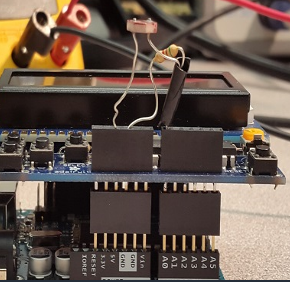
The picture below shows the completed circuit with the LDR and 5 kohm resistor in the LCD shield.
// select the input pin for the LDR
void setup() {
// declare the LDR as an INPUT
// init the Serial Monitor

void loop() {
// Read the analogue pin

// calculate the resistance

Serial.print(R); // light dependant resistance

}
End Of Post


")


