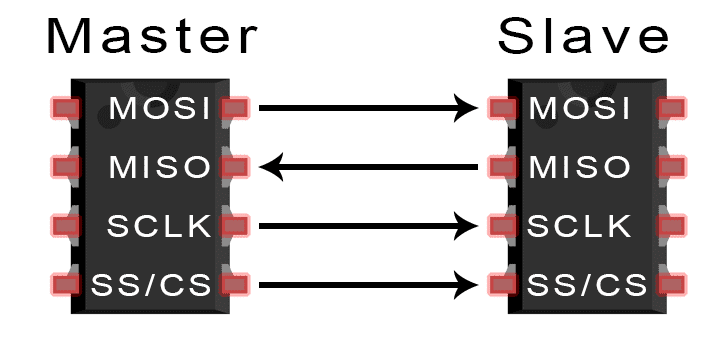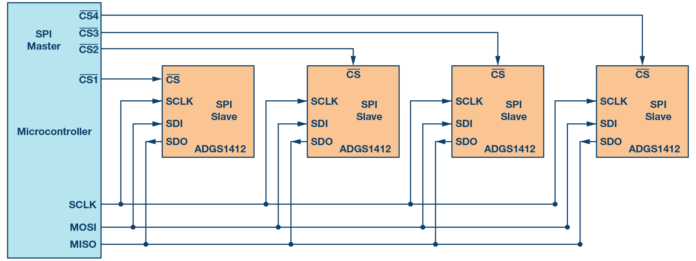
When you connect a microcontroller to a sensor, display, or other module, do you ever think about how the two devices talk to each other? What exactly are they saying? How are they able to understand each other?
Communication between electronic devices is like communication between humans. Both sides need to speak the same language. In electronics, these languages are called communication protocols. Luckily for us, there are only a few communication protocols we need to know when building most DIY electronics projects. In this series of articles, we will discuss the basics of the three most common protocols: Serial Peripheral Interface (SPI), Inter-Integrated Circuit (I2C), and Universal Asynchronous Receiver/Transmitter (UART) driven communication.

First, we’ll begin with some basic concepts about electronic communication, then explain in detail how SPI works. In the next article, we’ll discuss UART driven communication, and in the third article, we’ll dive into I2C.
SPI, I2C, and UART are quite a bit slower than protocols like USB, ethernet, Bluetooth, and WiFi, but they’re a lot more simple and use less hardware and system resources. SPI, I2C, and UART are ideal for communication between microcontrollers and between microcontrollers and sensors where large amounts of high speed data don’t need to be transferred.
Serial vs. Parallel Communication
Electronic devices talk to each other by sending bits of data through wires physically connected between devices. A bit is like a letter in a word, except instead of the 26 letters (in the English alphabet), a bit is binary and can only be a 1 or 0. Bits are transferred from one device to another by quick changes in voltage. In a system operating at 5 V, a 0 bit is communicated as a short pulse of 0 V, and a 1 bit is communicated by a short pulse of 5 V.
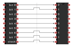
The bits of data can be transmitted either in parallel or serial form. In parallel communication, the bits of data are sent all at the same time, each through a separate wire. The following diagram shows the parallel transmission of the letter “C” in binary (01000011):
In serial communication, the bits are sent one by one through a single wire. The following diagram shows the serial transmission of the letter “C” in binary (01000011):
Disadvantages
- Uses four wires (I2C and UARTs use two)
- No acknowledgement that the data has been successfully received (I2C has this)
- No form of error checking like the parity bit in UART
- Only allows for a single master
End Of Post


